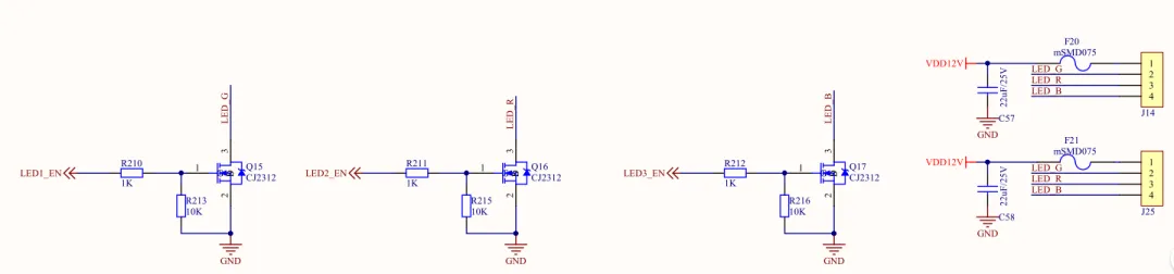
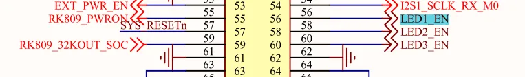
查看原理图,根据引脚分配表,找到led的gpio控制引脚。
led子系统
LED驱动可以直接采用gpio子系统或led子系统两种方式控制。此处采用led子系统,要确保内核启用了led子系统。
配置使能LED子系统:Device Drivers –> LEDs support
内核中设备树参考文档:kernel/Documentation/devicetree/bindings/leds/leds-gpio.txt
编写设备树节点
leds: leds { compatible = "gpio-leds"; work_led: work { label = "work_led"; gpios = <&gpio0 RK_PC0 GPIO_ACTIVE_HIGH>; linux,default-trigger = "heartbeat"; }; run_led: run { label = "run_led"; gpios = <&gpio0 RK_PA5 GPIO_ACTIVE_HIGH>; linux,default-trigger = "heartbeat"; };};gv_leds: gv-leds { compatible = "gpio-leds"; pinctrl-names = "default"; pinctrl-0 = <&gv_leds_gpio_fun>; status = "okay"; led1_u: led1-u { label = "led1_up"; gpios = <&gpio0 RK_PB0 GPIO_ACTIVE_HIGH>; default-state = "off"; }; led1_d: led1-d { label = "led1_down"; gpios = <&gpio0 RK_PB5 GPIO_ACTIVE_HIGH>; /* Keep LED on if BIOS detected hardware fault */ default-state = "off"; }; led2_u: led2-u { label = "led2_up"; gpios = <&gpio0 RK_PB6 GPIO_ACTIVE_HIGH>; /* Keep LED on if BIOS detected hardware fault */ default-state = "off"; }; led2_d: led2-d { label = "led2_down"; gpios = <&gpio0 RK_PC5 GPIO_ACTIVE_HIGH>; /* Keep LED on if BIOS detected hardware fault */ default-state = "off"; }; led_rgb_1: led-rgb-1 { label = "led_rgb_1"; gpios = <&gpio1 RK_PB0 GPIO_ACTIVE_HIGH>; /* Keep LED on if BIOS detected hardware fault */ default-state = "off"; }; led_rgb_2: led-rgb-2 { label = "led_rgb_2"; gpios = <&gpio1 RK_PB1 GPIO_ACTIVE_HIGH>; /* Keep LED on if BIOS detected hardware fault */ default-state = "off"; }; led_rgb_3: led-rgb-3 { label = "led_rgb_3"; gpios = <&gpio1 RK_PB2 GPIO_ACTIVE_HIGH>; /* Keep LED on if BIOS detected hardware fault */ default-state = "off"; };};
compatible属性:设备树和led子系统匹配的属性,表示这些led使用led子系统。
pinctrl-names属性:指定在不同状态下使用不同的引脚配置,这里是default,也就是pinctrl-0指定的属性。
pinctrl-0:pinctrl-names为default值时的引脚配置,这里值是gv_leds_gpio_fun。
status:表示使能该节点,若想禁用设置修改okay为disable即可。
label属性:系统将根据led子节点中的label属性在sysfs中生成相应的目录和设备文件。
gpios属性: 该属性指定了控制此led的是哪一个引脚。
更多属性配置参考内核中文档。
在pinctl节点增加gpio的配置:
gv-leds { gv_leds_gpio_fun: gv-leds-gpio-fun { rockchip,pins = <0 RK_PB0 RK_FUNC_GPIO &pcfg_pull_up>, <0 RK_PB5 RK_FUNC_GPIO &pcfg_pull_up>, <0 RK_PB6 RK_FUNC_GPIO &pcfg_pull_up>, <0 RK_PC5 RK_FUNC_GPIO &pcfg_pull_up>, <1 RK_PB0 RK_FUNC_GPIO &pcfg_pull_up>, <1 RK_PB1 RK_FUNC_GPIO &pcfg_pull_up>, <1 RK_PB2 RK_FUNC_GPIO &pcfg_pull_up>; };};
如果后续不需要使用只需要将gv_leds设备节点status状态设置为disable。
在实现过程中,部分引脚被占用找到没有生成led的sysfs文件,需要解除引脚占用:
a) 配置内核禁用TouchScreen
b) 禁用以下设备树节点
vcc3v3_lcd1_n: vcc3v3-lcd1-n { compatible = "regulator-fixed"; regulator-name = "vcc3v3_lcd1_n"; regulator-boot-on; regulator-min-microvolt = <3300000>; regulator-max-microvolt = <3300000>; enable-active-high; gpio = <&gpio0 RK_PC5 GPIO_ACTIVE_HIGH>; vin-supply = <&vcc3v3_sys>; status = "disable"; regulator-state-mem { regulator-off-in-suspend; }; };&wireless_bluetooth { compatible = "bluetooth-platdata"; clocks = <&rk809 1>; clock-names = "ext_clock";//wifi-bt-power-toggle; uart_rts_gpios = <&gpio2 RK_PB1 GPIO_ACTIVE_LOW>; pinctrl-names = "default", "rts_gpio"; pinctrl-0 = <&uart8m0_rtsn>; pinctrl-1 = <&uart8_gpios>; BT,reset_gpio = <&gpio3 RK_PA0 GPIO_ACTIVE_HIGH>; BT,wake_gpio = <&gpio3 RK_PA2 GPIO_ACTIVE_HIGH>; BT,wake_host_irq = <&gpio3 RK_PA1 GPIO_ACTIVE_HIGH>; status = "disable";};&pcie3x2 { reset-gpios = <&gpio2 RK_PD6 GPIO_ACTIVE_HIGH>; vpcie3v3-supply = <&vcc3v3_pcie>;status = "disable";};
将这些节点的status属性设置为”disable”。
用户空间访问
root@M3:~# ls /sys/class/leds/led_rgb_1/ led_rgb_2/ led_rgb_3/ mmc0::/ run_led/ work_led/root@M3:~# ls /sys/class/leds/led_rgb_1/brightness device max_brightness power subsystem trigger ueventroot@M3:~# ls /sys/class/leds/led_rgb_2/brightness device max_brightness power subsystem trigger ueventroot@M3:~# ls /sys/class/leds/led_rgb_3/brightness device max_brightness power subsystem trigger uevent
通过读写brightness属性就可以控led点亮/关闭。

 10个月宝宝每天需要喝多少奶粉?
