什么是Device Tree(设备树)
嵌入式系统包含多样的组件与架构,需要一种高效的方法以标准化、可复用的格式来描述硬件。Linux设备树(Device Tree, DT)为此提供了一种灵活的结构,能够以操作系统和引导加载程序可解析的方式定义硬件细节。下面我们将深入探讨设备树的工作原理、其重要性以及整体结构,这是理解Camera驱动的必备的前导知识。
Typical Embedded Platform为什么需要Device Tree
嵌入式的设备中,按照自发现性分为:
- 自发现硬件(Discoverable Hardware),典型的如USB,蓝牙设备;
- 不可发现硬件(Non-Discoverable Hardware)典型的如I2C,SPI等总线设备。
对于不可发现硬件,在嵌入式系统中,普遍使用Device Tree ,它是一种开放的标准规范,由devicetree.org 负责维护(Release v0.4 · devicetree-org/devicetree-specification),来描述关于硬件布局的基本细节:
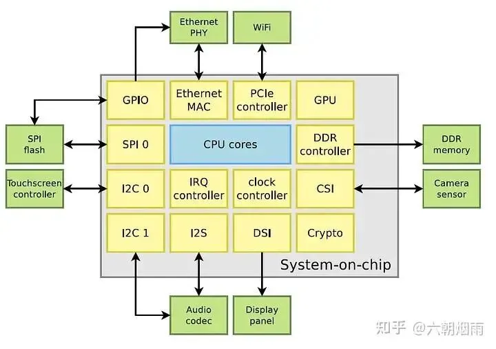
- CPU Cores:例如,一个系统可能包含两个Cortex-A9核心;
- Memory Mapped Controllers:设备特定的细节,例如UART、I2C及其他控制器的内存地址和中断请求;
- Board-Level Components:连接到特定SoC总线的外部组件,例如音频编解码器,并包含有关从设备地址、时钟源和复位信号等详细信息;
Device Tree是怎么工作的?
Device Tree的结构
Device Tree通过树形结构描述硬件信息,并由内核在启动时解析,用于驱动绑定和硬件初始化:
- 根节点
/:系统整体描述。 - SoC 节点:CPU、总线(I2C/SPI)、外设控制器。
- 外设节点:每个硬件模块,例如 GPIO、I2C 设备、SPI 设备、Camera Sensor。
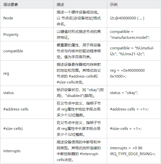
- 属性(Properties):寄存器地址、时钟、GPIO 引脚、兼容字符串(
DT 文件通常是 .dts(Device Tree Source)或 .dtsi(include 文件)。
Kernel解析流程
- 内核启动时加载 DTB(Device Tree Blob);
Device Tree语法
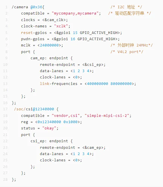
以CPU节点作为示例
/ { cpus { #address-cells = <1>; #size-cells = <0>; cpu0: cpu@0 { compatible = "arm,cortex-a9"; device_type = "cpu"; reg = <0>; }; cpu1: cpu@1 { compatible = "arm,cortex-a9"; device_type = "cpu"; reg = <1>; }; };};
Camera相关结点Device Tree
节点解析
关于port / endpoint和remote-endpoint会在下一篇:V4L2架构中专门介绍。
| |
|---|
| Camera Sensor 节点,通常挂在 I2C 总线上 |
| |
| |
| |
| |
| |
| |
| 连接 Sensor endpoint,实现管道绑定 |
| |
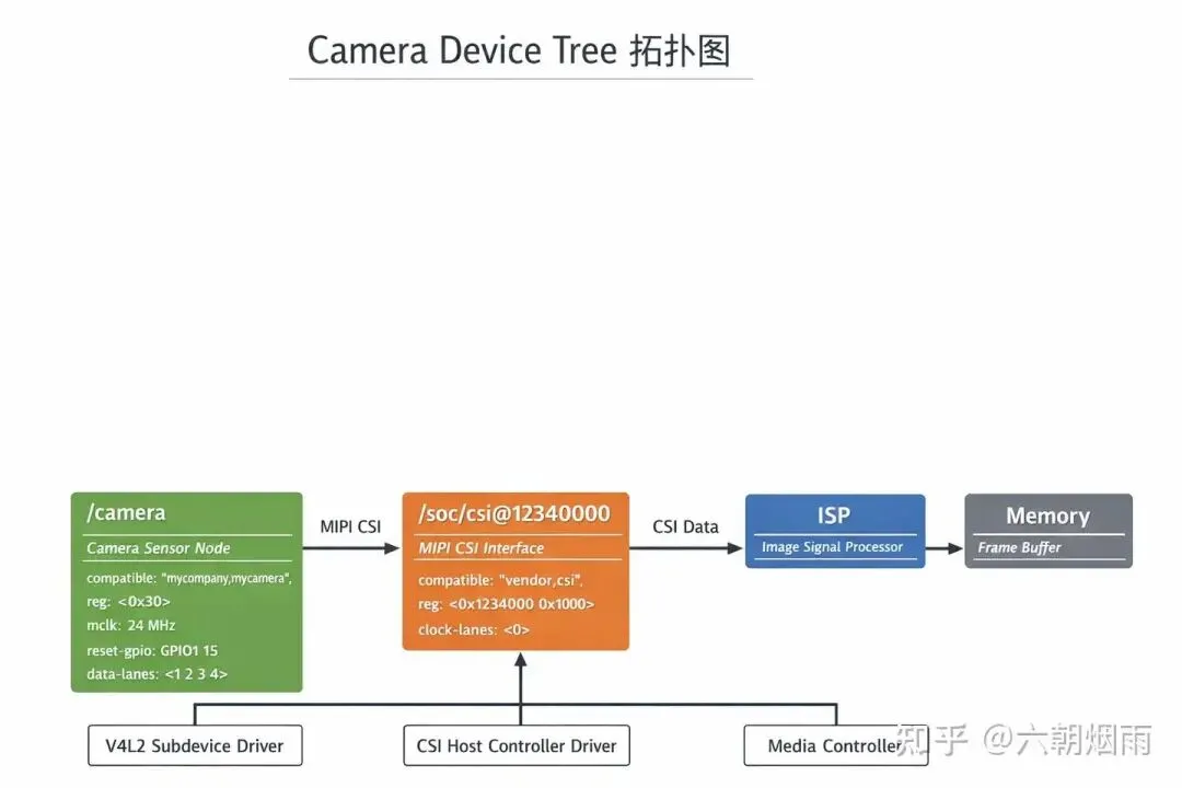
Linux下Camera的device tree拓扑图驱动绑定
- Sensor 节点
compatible → 对应 V4L2 Subdevice 驱动 (会在下一篇:V4L2架构中专门介绍) - CSI 节点
compatible → 对应 CSI Host Controller 驱动
媒体管道描述 (会在下一篇:V4L2架构中专门介绍)
Media Controller 根据 endpoint 构建管道拓扑:
Sensor → CSI → ISP → Memory
如何查看Linux系统的Device Tree拓扑以及编译方法
查看:
dtc -I dtb -O dot -o device_tree.dot /proc/device-tree/system.dtb
编译:
dtc -I dts -O dtb -o my_camera.dtb my_camera.dts
参考文献
Release v0.4 · devicetree-org/devicetree-specification
 10个月宝宝每天需要喝多少奶粉?
